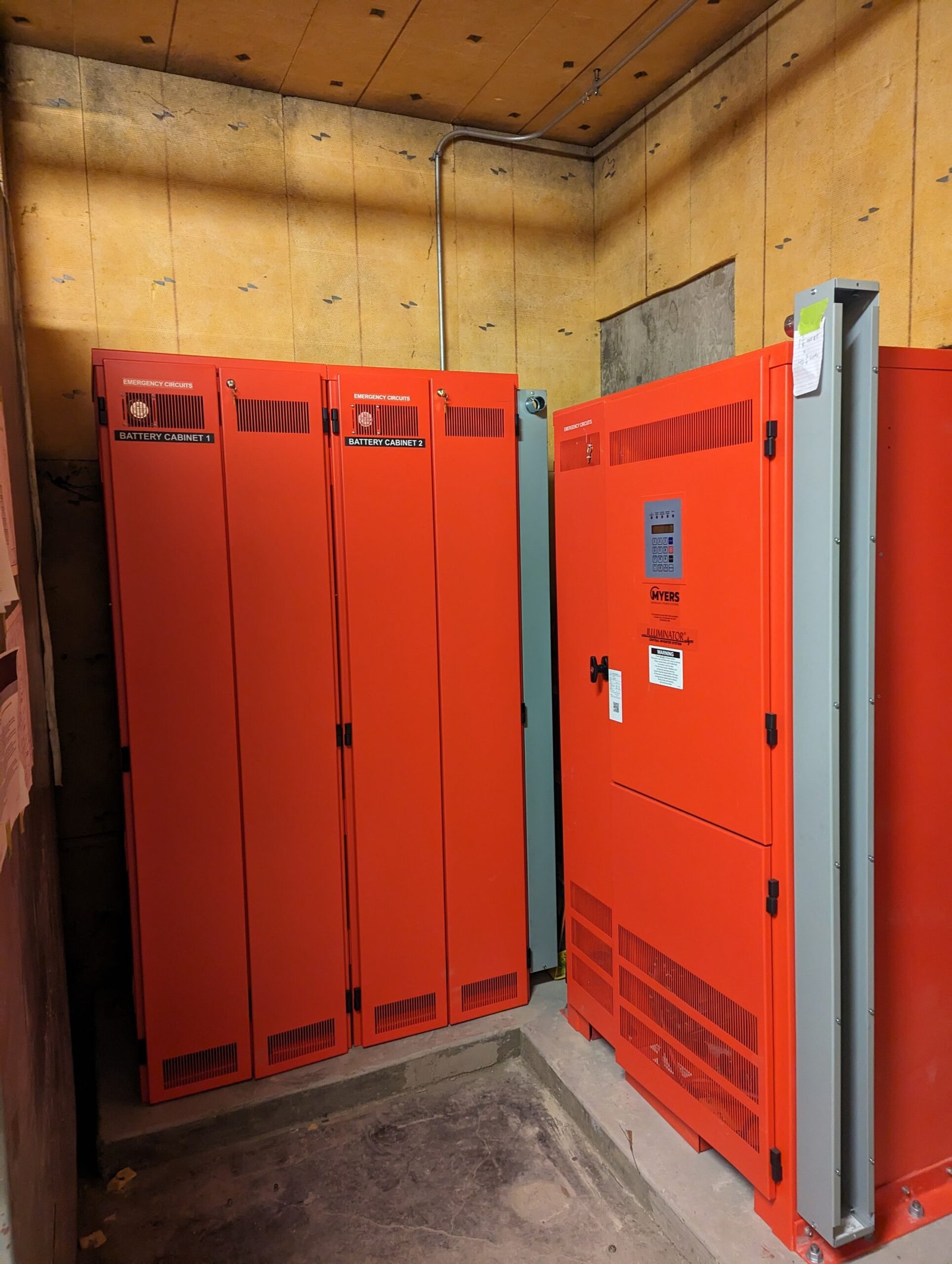
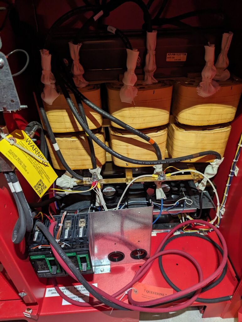
We are installing a 33.2 KW/KVA Myers emergency power system inside of the building we’re working on. The equipment we call an inverter consists of two battery cabinets and one electronics cabinet which is divided into two sections.
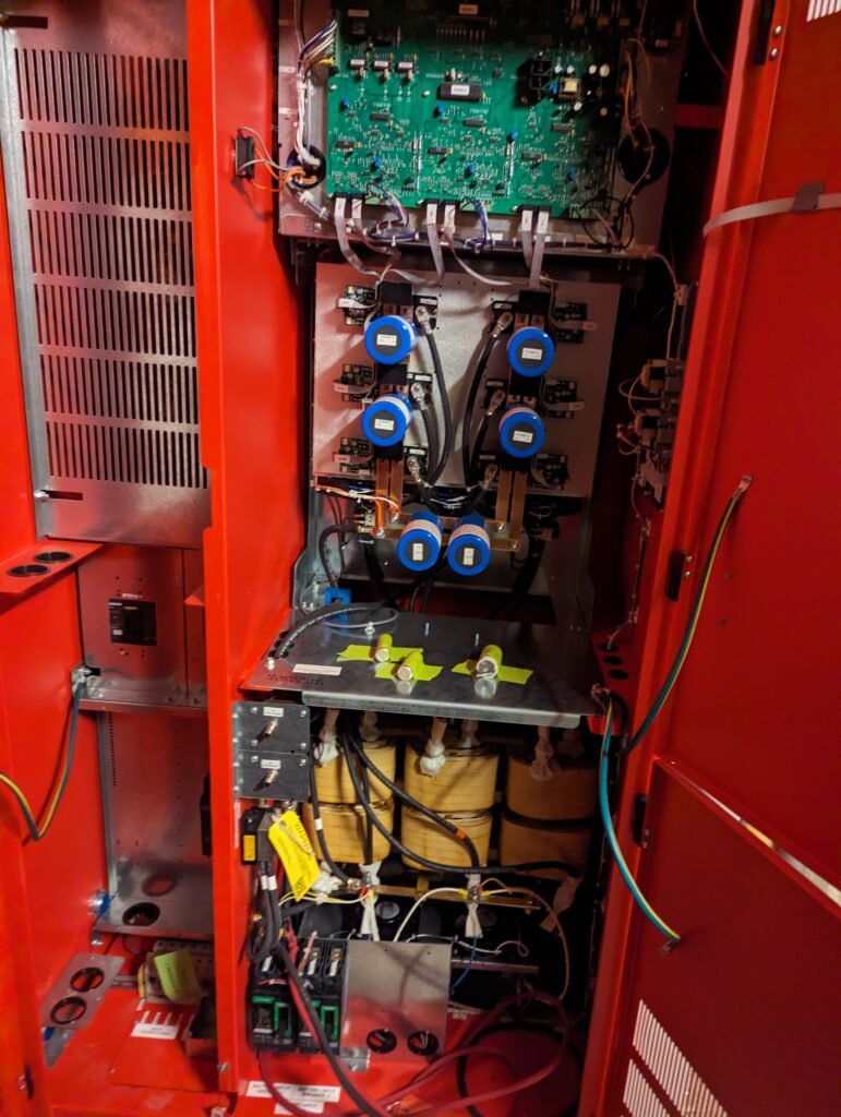
Emergency lighting inverters provide power to lights and other devices when there is a utility power outage. AC voltage and current are supplied to this inverter through four #2 conductors which land on the “input” terminal block in the electronics cabinet. Different sized inverters will require different sized conductors depending on the size of the breakers supplying them.
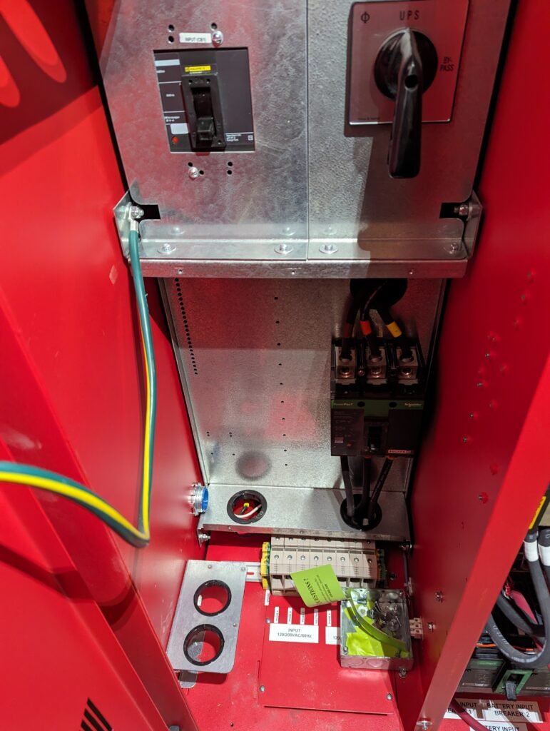
We have a 120/208V service in this building and this inverter is being fed by a 100A 3-pole breaker.
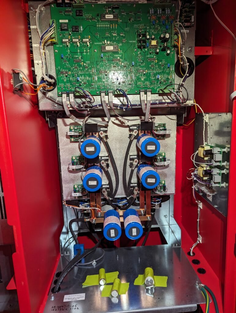
There is an internal automatic transfer switch inside the inverter, as long as the inverter senses power from the utility it passes AC voltage through to the load and also changes AC voltage to DC through a converter to constantly charge the forty 12V batteries.
Once utility power stops, the inverter senses this and the internal automatic transfer switch will change position. The charged 12V batteries will now push their DC voltage and current through the electronic components, and out of the “output” terminal block will come AC voltage and current to the load.
This all happens in a matter of seconds so the lights will only briefly blink.
Once utility power is restored the inverter senses it and then the automatic transfer switch switches back to utility power.
That’s how inverters work in a nutshell.